LED Panel
Raspbery Pi and LED
During quarantine, I got myself a Raspberry Pi for my birthday to tinker around with. This was my first Raspberry Pi and decided to get it after taking my introductory course to Python. With my newly gained Python skills, I had the idea to work on a project since I stopped going to work due to COVID-19. I figured this would be a fun way to keep me busy and I could learn more about electronics. Work on this project was pushed back due to other projects, waiting on parts, and the start of the Fall semester.
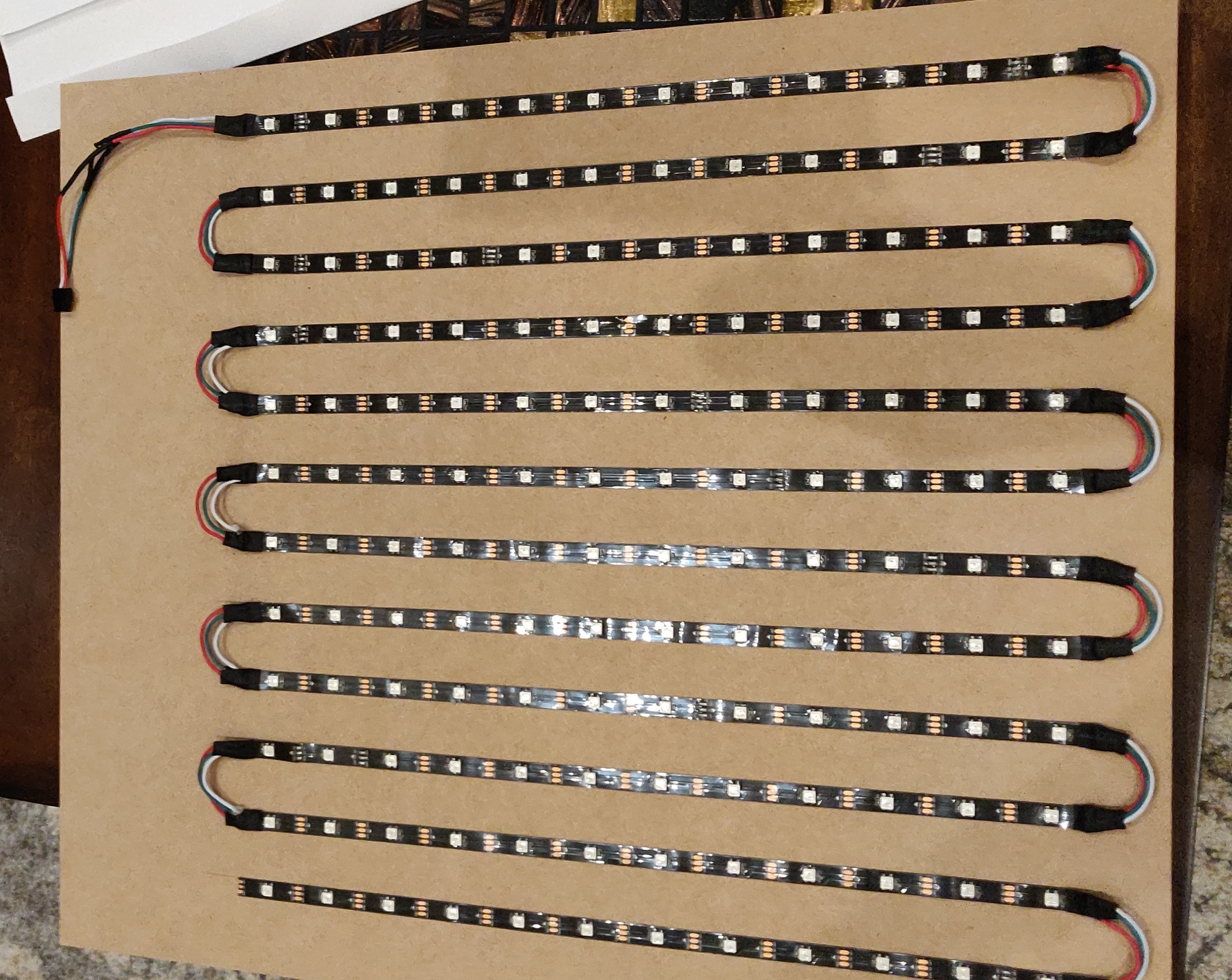
After playing with the Raspberry Pi a bit, I had to decide on the actual project and browsed the web for ideas. Since I was still a beginner and considering the cost of a lot of projects seen online, I decided to build an LED panel. The panel is relatively cheap and it could be used as a learning tool with the code for lighting animations. Examples online showed people making more complicated variants such as a table or a gigantic wall of LEDs. I decided to build a 12x12 grid because of the low price on a 150 LED reel. Since there are 150 LEDs, I chose to use 144 of them for a 12x12 grid and have 6 backups.
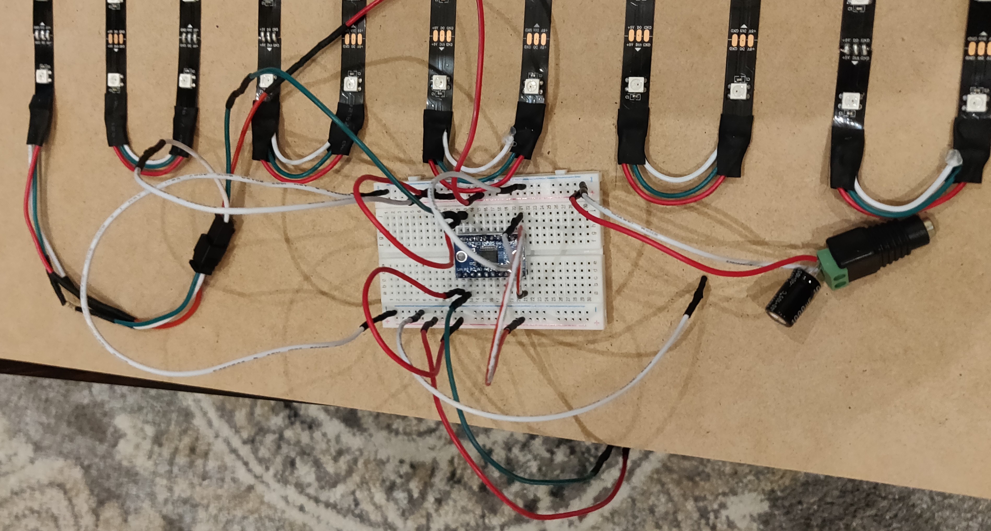
I chose to use WS2812B LED strips since they are individually addressed and easy to work with. I found a wiring schematic online to follow. I looked at various examples to get an idea of what parts to gather and did calculations for my application to determine what wire gauge to order. I believe my system is limited by the solderless breadboard, which is rated for about 5 amps, I chose to use 20 AWG wire just as a personal safety factor and in case of future modification. I ordered a pack of jumper wires to do a couple small preliminary tests since I was new to all this, but later made my own custom wires. The jumpers were about 28 AWG so they were way too small for my project. So, I took the Dupont connectors of the jumpers and put them onto strips of my 20 AWG wire.
I had to experiment a bit since my parts were slightly different than the parts listed on other projects online. Currently, the setup is wired correctly and works. Now, the main issue is to figure the code. Originally, my idea was to include a camera module which would recognize peoples emotions based on facial recognition and those readings would act as inputs into an emoji animation. For example, if someone frowns in front of the camera, facial recognition software would read "sad" and that would be used as an input to run the Python script to display a sad face on the panel. That is the eventual goal, but I need to focus on the actual animations first to understand how it works.
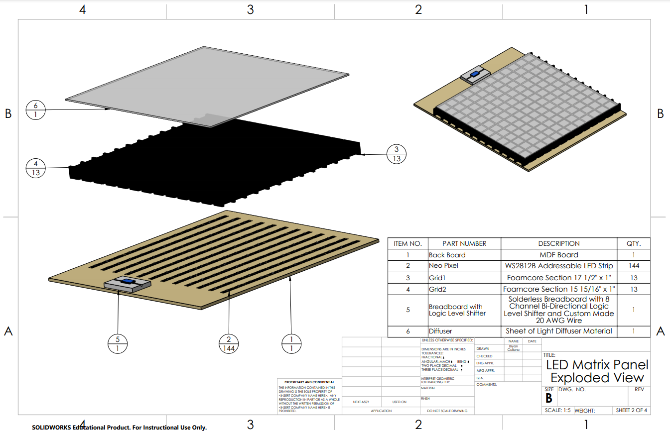
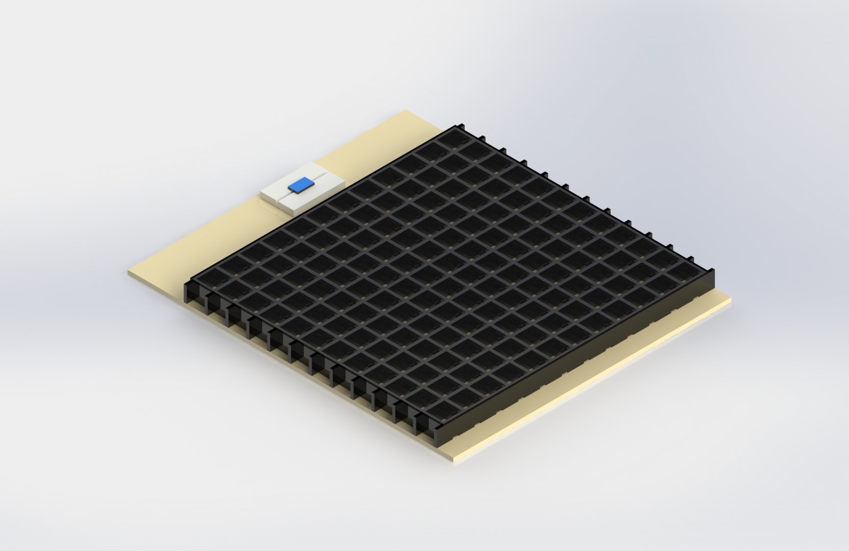
The picture on the right shows the drawing and exploded view of the assembly.